Mar 01, 2018
Most in the satellite industry are familiar with the term HTS or (High Throughput Satellite), and more and more of them are being deployed all the time, but this technology is still unknown to many clients and customers. What is different about an HTS satellite? Why is this an important development?
The classification HTS primarily refers to a large jump in capacity ranging from twice as much, to more than 20 times as much capacity as a classic FSS (Fixed Satellite Service). The net effect is a significant drop in the cost per bit. One of the first HTS satellites, ViaSat-1, launched in 2011, had more capacity at that time, than all the other commercial satellites covering North America, combined. A typical FSS with a payload of 24 C-band transponders (36 MHz each), and 24 Ku –band transponders (36 MHz each) will provide a total of 1.7 GHz of bandwidth, which yields a little over 3 Gbps of capacity when used for data. By comparison Intelsat’s IS-29e, one of its first HTS deployments, supports 20 – 60 Gbps of capacity.
To gain these efficiencies, HTS leverages “frequency reuse” and “multiple spot beams” to increase throughput, regardless of the spectrum choice (Ku, Ka, V-band, etc.). Let’s examine these features.
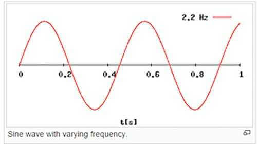
The speed of information delivery is measured in bits/sec and has two components. First is the bandwidth, or size of the pipe. This is measured in MHz, and as will be discussed, frequency reuse has increased the size of the pipe. The other component is efficiency or the bits/sec per MHz. This is the amount of error-free content in the data pipe. For a satellite operator there are two conflicting goals – maximize the total amount of bandwidth the satellite can deliver, or maximize the individual circuit throughput. The trade-off will depend on the business applications the satellite provider most wants to address.
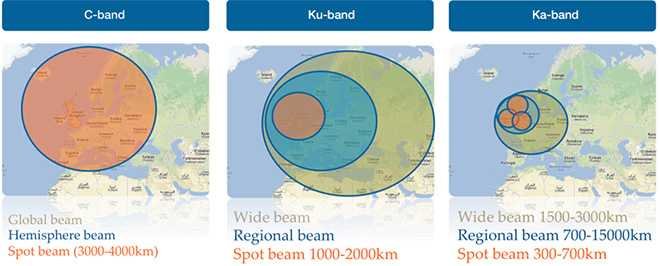 Credit: Newtec
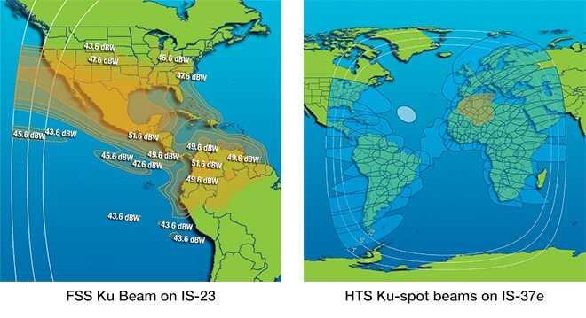
A key difference between FSS and HTS is the size of their beams or footprints on the ground. FSS beams are few and they are large, covering entire continents or large regions of ground. Large beams spread the available RF (radio frequency) power across a wide geographic area. This results in what is referred to as a low spectral efficiency (a weak signal) but one that comes with the advantage of covering a large area. HTS, instead, puts up many smaller “spot beams” with smaller footprints, each covering smaller regions. Each of these smaller beams will have a higher spectral efficiency (good signal strength), and can therefore support higher speeds.
How is this done? A large traditional FSS footprint is called a wide beam, and it is based on one frequency. The entire geographic region covered by the wide beam must be supported by this one frequency, and this frequency can’t be used again by the satellite, anywhere within this geographical area or there will be interference. The satellite, therefore can only use the frequency once. The HTS approach is different. Instead of a wide beam, a larger number of smaller spot beams covering smaller areas of geography are deployed, using techniques similar to those used by the cellular industry. Each beam will use a different frequency, and each frequency is capable of providing a large chunk of bandwidth.
If these spot beams are laid out in a pattern in which a frequency used in one spot is far enough from another spot so it won’t interfere, the frequency can be used again. This provides a huge increase in capacity. The same frequency can be used to service two or more separate geographies and sets of clients. This requires some design work on the part of the satellite operator, just as for cellular operators. The idea is to lay out the frequencies so that they can be reused in different areas, again and again, but making sure they are far enough apart from each other to prevent interference, as this reduces their efficiency.
Spot beams provide more power (MHz) and therefore drive efficiency up, but if they are close to another beam of the same frequency, this reduces efficiency due to increased interference. If greater distance can be obtained between beams of the same frequency, those spot beams will increase in efficiency, but this will reduce the amount of frequency reuse, and thus reduce the total throughput of the satellite. Like most things in the satellite business, squeezing the balloon here, makes it expand over there. How to lay out the spot beams on a geographic grid is a business decision. One can design for servicing a lot of users with a lower efficiency, and thus a lower speed, service – such as might be used for consumer broadband subscribers, or the satellite can be configured to support a smaller number of large carrier-grade, high efficiency services, such as might be used for MNO (Mobile Network Operator) and WISP (Wireless Internet Service Provider) backhaul circuits.
The network architecture also changes with HTS. In a typical FSS scenario, the satellite operates in what is referred to as a “bent pipe” configuration. This means that the satellite is operating like a “mirror” or “relay” taking whatever comes up to it, and sending it back down to earth with no changes. FSS can do this anywhere within the large regional beam. Any two stations within a large geographical area can connect to each other in this way. For HTS, this architecture doesn’t really work. First, the “bent pipe” would only apply within each small spot beam, so sites sharing the same beam would have to be in close geographic proximity to each other. Therefore HTS takes on a more centralized approach, and in so doing, leverages additional efficiencies.
With HTS, instead of simply acting as a relay, the satellite regenerates the signal that is sent back to a central hub or “Gateway” on the ground. That means it can take traffic coming and going to large number of individual sites, all using slightly different portions of the spot beam frequency (carriers) and aggregate (combine) the customer site traffic, then forward it in a new transmission that treats a central spot beam as one large carrier or pipe to the Gateway, for a connection to the internet backbone. In the process of regenerating or aggregating the signal, all the little pieces of wasted capacity between and among these separate circuits can be reduced, thereby gaining transmission efficiencies that create more capacity, which translates to higher data rates.
HTS is a piece of “NewSpace” that is here and is actively being deployed to the benefit of customers and operators alike. Challenges remain. There is great interest in using HTS for mobile applications such as the airline industry, remote control of drones, maritime applications, connected cars, etc. This will come as flat panel antenna (FPA) development continues and prices will come down as volumes increase. In the words of BTO (Bachman Turner Overdrive), the 1970’s rock band, “You Ain’t Seen Nothin’ Yet!”