BusinessCom Antenna Alignment Basics
Oct 16, 2020
It is frustrating for partners, clients, and NOC Engineers when VSAT activation attempts fail due to low downlink signal levels. For those out in the field, often in difficult circumstances, “good enough” might seem sufficient, but in the satellite business it is not. The NOC is unable to accept remote sites into a network if they do not reach minimum required RF levels. This is necessary to deliver a good quality of service and ensure that there is enough signal margin to overcome bad weather conditions. Additionally, the NOC must pass various tests with the satellite operator to ensure that VSAT terminals do not produce interference on opposite transponders or other adjacent (nearby) satellites.
There can be several reasons why an acceptable SNR (Signal to Noise Ratio – measured in dB) may be difficult to obtain. This article will review some key points to assist in that effort.
Examine Equipment
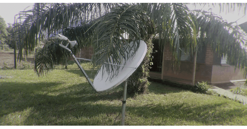
First, make sure the antenna reflector is in good shape. The reflector surface must be clean, without any cracks, dents, chips, or other physical damage. Even small, barely visible deformations may result in significant signal level degradation. Make sure feed boom and support arms are not bent, even a little. The feed must have no hints of rust inside and all the waveguide joints should be properly sealed, with gaskets in good condition and the feed properly weatherproofed. If this is used equipment, make sure seals are good and nothing is cracked and that there is no condensation inside the feedhorn. If you are installing used equipment, take a quick look at our article, The Care and Feeding of VSAT Antennas to ensure that your hardware is in good condition.
Line of Sight
You must have a clear line of sight to the satellite. Trees, vegetation, building structures, mountains, etc. must not come in between the antenna and the satellite. It might not seem like much, but a tree branch or other foliage will often cause a significant weakening of the signal, i.e. attenuation. Double check the site survey results and find a location with a clear line of sight or remove any obstacles in the way. The NOC can provide a Site Survey form to assist in preparing for an installation.
Cables and Connectors
Cabling is often the source of connectivity problems. For existing installations, corrosion, wear and tear or other damage to cable and connectors might have increased attenuation, causing the signal to drop or be a source of increased noise. Always use the correct, good quality cables, and keep the coaxial cable run overall distance below 30 meters (assuming RG-6 cable). Make sure the cables are in good condition. Connectors should have no rust or moisture, and cables must have no hard bends, which can result in the center conductor cracking and then producing intermittent problems. Note that cable performance naturally degrades with time, and it is easy to lose a few decibels of signal on old cables, especially at termination points and sharp bends. You can make a test cable kit 2-3 meters long and connect the modem right next to the antenna with a short test RX (receive) cable during the pointing. Confirm signal levels after connecting the longer cable leading into the building where the modem will be housed. The NOC can provide a document detailing best practices for installing and terminating coax cables.
Spares
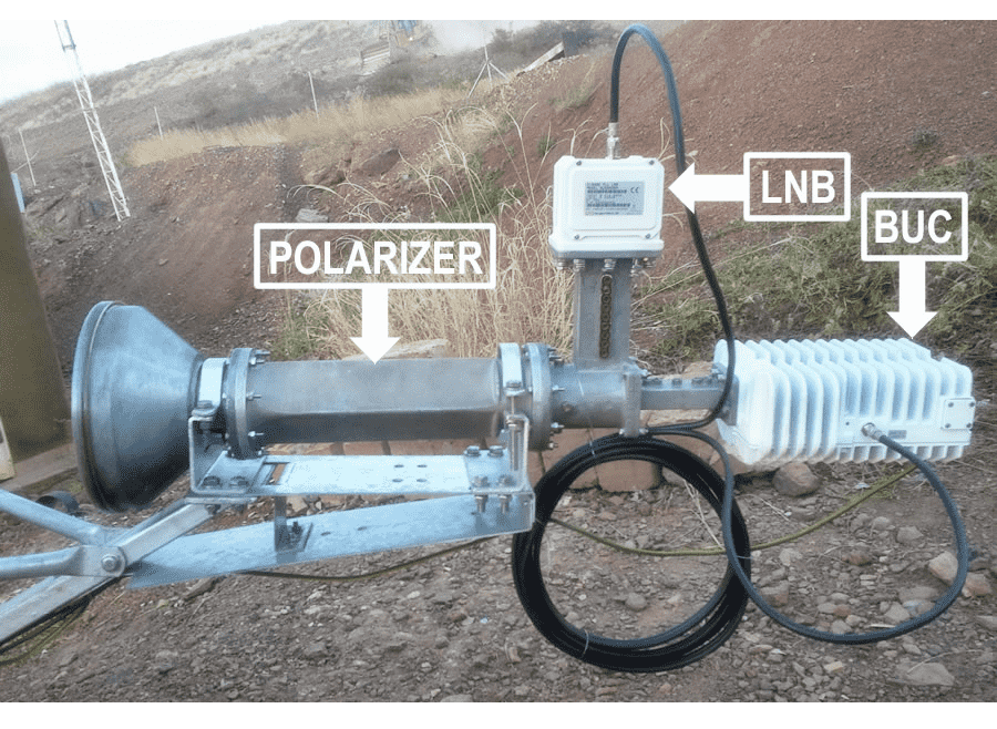
A spare LNB (Low Noise Block), which is the receiver, is always a good idea, especially if you are using second-hand components. An LNB is an active device (low noise down converter and amplifier built-in and powered via the receive cable from the modem). Since LNB’s have active components, they may have increased noise or problems with local oscillator stability which may cause frequency drift. This in turn will make it difficult or impossible to properly align the antenna. Note that it is a good idea to have a spare BUC (Block Up Converter) or transmitter, as well as spare modem, but from an alignment perspective, the LNB is what you are working with, and it’s the least expensive of the electronic components.
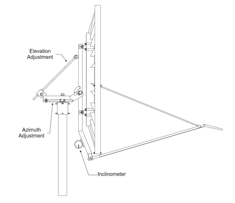
Leveling
This is more important than one might think. It is exceedingly difficult, if not practically impossible to align an antenna that is mounted on a pole that is not perfectly plumb or level. If using a pole mounted in a cement base, be sure to drill a hole near the bottom of the pole and insert a bolt or piece of rebar that extends into the cement on both sides of the pole so it cannot twist with the wind. If using a mount, make sure your antenna mount is levelled precisely, and that it is perfectly vertical. Use a bubble level to make sure there is no tilt. It is essential that the antenna mast be levelled, any inclination of the antenna mount will cause antenna movements on all axis at the same time, such that when you are locked on elevation (up/ down) and moving the azimuth (left/right) on a tilted mount, your elevation and polarization will be drifting with each azimuth movement. This will make precise antenna pointing almost impossible even for a professional and experienced technician.
Mast/Pole Assembly
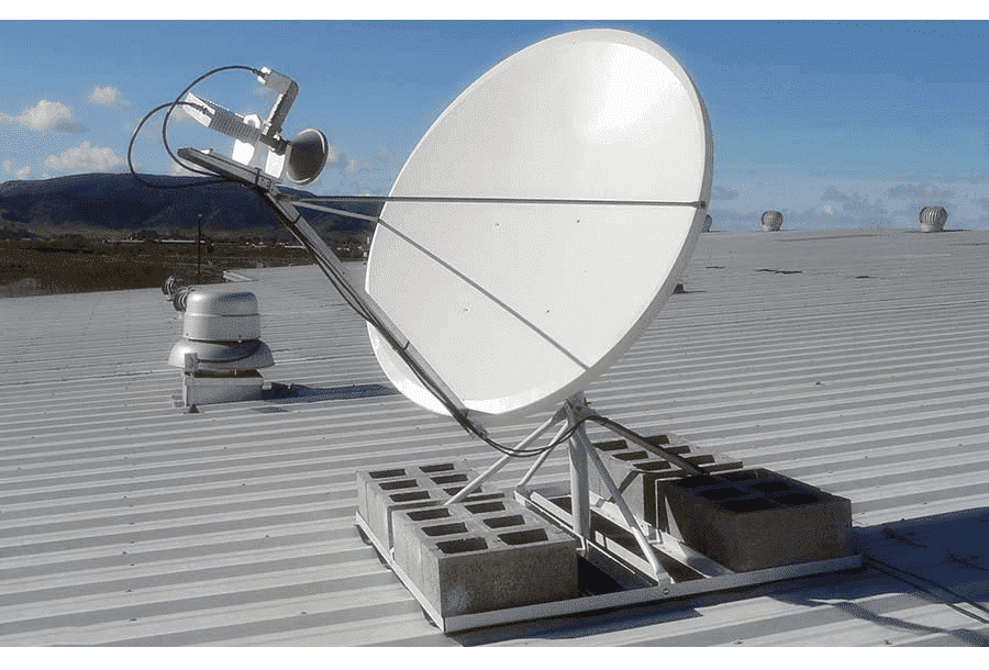
The mast should be the proper diameter, as required by the antenna manual, and should be in good shape. If you are not sure which diameter is needed, please ask our NOC. Sometimes a mast with grooves where the antenna mount cap bolts grind into it may result in the whole antenna mount wiggling after the bolts are tightened, which leads to signal problems later, especially due to wind load. If you suspect your mast has grooves, you may want to cut off a short piece to make sure the cap bolts grind into a flat surface and hold the antenna fixed under expected wind conditions. In the case of a Non-Penetrating mount, add Ballast such as concrete blocks, per the manufacturer’s directions, so the antenna does not move. Make sure the antenna is perfectly rigid and fixed after the initial rough alignment.
Antenna Assembly
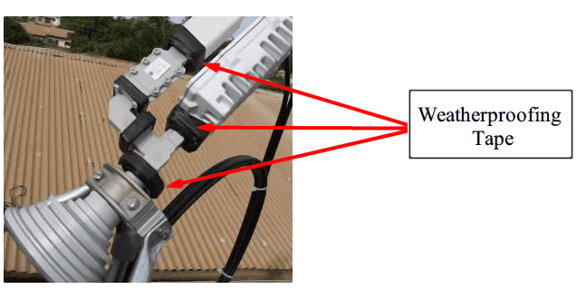
It is always good to know your exact antenna model. Ensure that you have the assembly manual and follow the guide. One by one, check off the assembly steps and make sure your assembly is correct and nothing is mismatched. If you do not have the manual, let us know know your antenna model, and we will help you with the assembly manual. If there are issues aligning the antenna, it will be very useful to have antenna assembly photos including close-up shots of the feedhorn assembly, antenna mount, antenna general views from different angles, and a photo from the back of the antenna in the direction the satellite is pointing, so the NOC has a view of the line-of-sight to the satellite. All connection points should be protected with weatherproof tape.
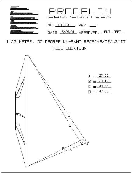
Make sure the feed is assembled exactly as per the antenna manual. Confirm that you are using the same bolt openings on the feed boom as instructed in the antenna manual, and all the feed components are installed in the required order. Some antenna models can allow the feed to be assembled incorrectly, which may result in the feed being tilted or installed too close or too far from the reflector surface. This ultimately results in the feed being out of reflector focus, so you are losing part of the antenna reflector surface to amplify satellite signals, which results in lower SNR. So-called antenna “ABCD” tests for some antenna models are available to test your feed geometry if in doubt. Our NOC can send you ABCD test details, however, it could also be useful for the NOC to examine your feed assembly carefully, so do not hesitate to send in close-up photographs the engineers can comment on.
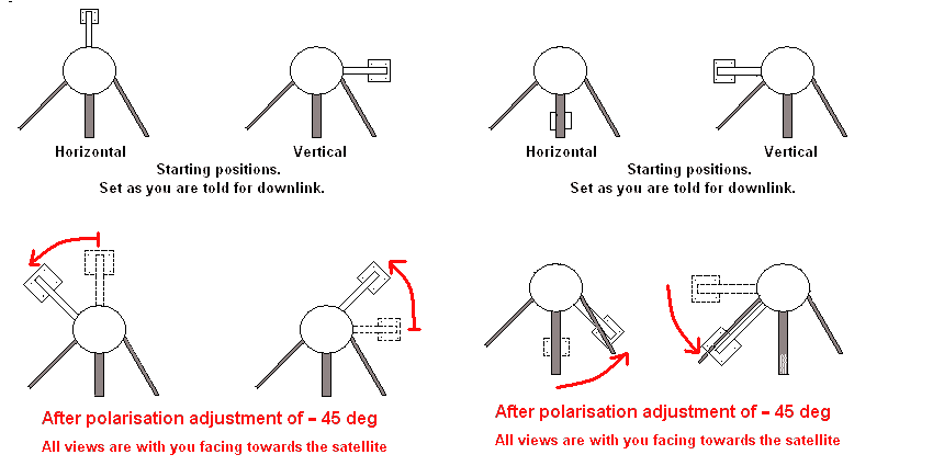
Polarization
For the initial, rough alignment, if the satellite polarization you are using is linear, tilt the feed polarization to the estimated value at your location. This tilt value should be provided by our NOC along with the options file. Do a small elevation adjustment, typically half a degree up or down, then do an azimuth sweep for rough alignment to the satellite. Repeat azimuth sweeps and adjust elevation by a small step each iteration
For C band installations, you will need to make sure you have the proper linear vs circular polarizer for your antenna:
Fine Tuning
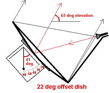
Sometimes it is difficult to fine tune an antenna. The first thing to confirm is that the antenna offset has been taken into account when pointing the antenna at the satellite. Most of the VSAT antennas we work with are offset antennas. That is, the antenna panel does not point directly at the satellite, but rather some number of degrees below it, depending on the antenna. The signal is reflected to the feedhorn, which is not in the middle of the antenna. Each antenna manufacturer is different. The NOC can help determine the proper offset if there is any question.
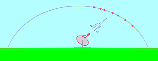
One reason installers may have difficulty getting a good receive signal, is because they have locked on the satellite’s side lobe. Any antenna has patterns, and there is a main lobe along with side lobes that produce lower gain. If you simply cannot get the signal to improve with small incremental changes in alignment, you may be lining up with a side lobe, rather than the main lobe, and may need to start over.
Here is an antenna alignment procedure that we recommend following once you check on all the above points. Once you set the antenna with initial angles (including ensuring the feed polarization angle has been set precisely), you need to fine-tune the antenna. Antenna fine-tuning steps:
- Put your antenna on the assumed elevation.
- Remove it at least 20 degrees away from the assumed compass bearing (azimuth)
- Very slowly, in very tiny increments, not more than 1-2 degrees at once, sweep the antenna in towards the required direction in azimuth slowly by little steps, continuously looking at the signal level obtained in the pointing tool.
- Following each small move, give the modem a couple of seconds to determine the signal – since we’re working with a digital and not analogue signal here, it takes some time for the modem to decode and lock onto it
- If this does not result in a signal level increase, change your elevation by 1-2 degrees up and repeat the same. If no effect – move a few degrees down on elevation repeating the same antenna sweep procedure.
Antenna fine-tuning may require time and patience from the installer, and you may not obtain good results with antenna pointing if you have problems with any of the points mentioned above.
Once the initial alignment is done, make sure to use the screws to fine-tune your antenna to the best possible SNR level. This is the most crucial step. Remember that the bigger the antenna, the smaller the beam width. Here are a few beam widths example just to give you the idea of the alignment accuracy required:
- 1.2 m antenna, Ku-band: 1.2 degrees.
1.8 m antenna, Ku-band: 0.8 degrees.
This means that with a 1.2 m antenna, you need to be within 1.2 degrees on the satellite beam’s center-box to achieve proper alignment. If you are half a degree off to one side then your signal drops by 3 dB, which is a significant loss of the power you receive from the satellite. This corresponds to a very small antenna movement. During the fine-tuning process you should be doing 1/4 or, sometimes, 1/8th or even 1/16th of a turn of the screw, depending on the antenna model. Often you cannot even see the antenna moving by the naked eye at this step. VSAT antennas are very demanding of precise alignment.
Hopefully, this is helpful. If you are unsure at any step, please send the NOC close-up and overview photographs of your antennas, as sometimes we might be able to help spot an issue. It often boils down to having good antenna, cables and connectors in good condition, a rigid and perfectly leveled mast, following proper instructions and, of course, an installer’s patience.